In the HVAC field various types of end devices are utilized to provide and receive information to control a
system. These devices transmit signals in either a binary or analog form. Binary signals are signals that
can only come back with 2 values. Think of a switch. Its either on/off, enable/disable or normal/alarm.
An analog signal, what this article will be focusing on, offers a continuous range of values for a given
parameter such as temperature, pressure, or humidity. When sending or receiving an analog signal, it is
typically categorized into two options: a voltage signal (0-10 Volts (V)) or a current signal (4-20 milliamps
(mA)). I will outline the differences and the advantages of choosing one over the other.
0-10V Signals
0-10V signals are more common in comparison to their 4-20mA counterparts. Almost every controller
can receive or send a 0-10V signal. One of the reasons for this can be due to cost as a 4-20mA signal end
device is more expensive to produce.
Voltage signals also have the benefit of being able to troubleshoot the signal wire without having to
break the communication line. This is because, in order to read the voltage signal, we would need to
wire the meter in parallel with the signal. For the milliamp signal, we would need to be in series with the
signal, meaning we would have to break the wire to test.

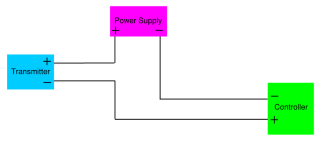
Another benefit is the ease of wiring for end devices with a voltage signal output. Looking at the diagram
below the wiring is straightforward. These end devices typically have two sets of termination ports: One
for power and one for the signal output.
This changes when you are wiring a 4-20mA circuit because current signal end devices typically only have
one set of termination ports. This can lead the end devices to be wired improperly and could damage
the end devices or in some cases the controller. Some manufacturers produce 4-wire configurations of 4-
20mA end devices (same wiring as voltage signal devices); however, these are not common.

4-20mA Signals
Apart from it being slightly more challenging to wire, current signals offer numerous benefits over
voltage signals. The first advantage is the ease of troubleshooting. No signal faults can be detected
immediately. In a current signal, 4mA is designated as true zero. This is so that there is enough power to
power the end device itself. The benefit that comes from this is that now if the BMS is reading 0mA we
know that there is a signal problem. Comparing this to a typical 0-10 voltage signal where there is no
way to differentiate. While there are 2-10 voltage signals that offer the ability to detect no signal faults,
they are less common.
4-20mA signals are also less susceptible to electrical interference or noise. This is because noise-induced
voltage fluctuations along the transmission line don’t directly affect the current flowing through the line.
The receiver will then have a resistor wired in to read the voltage through the resistor.
Another benefit is that there is no voltage drop. Wire possesses a small amount of resistance. The longer
the wire runs, the greater the resistance the wire has. This resistance in small wire runs is negligible and
will not cause a problem with your signal readings. The problem occurs when you have longer wire runs.
Long wire runs will increase the voltage drop and cause the BMS to read an incorrect value. Current does
not suffer from this, allowing the wire to be run further with no issues. I had this problem in a building
where the nearest control was on the first floor of an adjacent building. The customer wished to put a
current transducer (CT) on his VFD located on the 3rd floor of the building and the original CT spec had a
voltage output. The exact wire length was unknown so we would not have been able to offset the
voltage drop. Instead, we switched the CT with a current signal 4-20mA which fixed the problem and
gave the customer the added benefit of setting a no-signal alarm if the BMS reads 0mA.
Conclusion
It is important to take all factors into consideration when selecting the signal type to use when making a
device selection to address the needs of your specific application. When a voltage signal is used, factors
such as wire size and distance may need to be taken into consideration due to voltage drops. These
factors do not need to be taken into consideration when using a device that puts out a 4-20mA signal.
Each application is different and should be evaluated in an effort to ensure that the best solution is being
provided for the specific use case.


